
Cyberball - The Cybertruck-Inspired Pinball Machine
This was my senior design project for college. Michael Yip, a professor at UC San Diego. My partner, Adin Ackerman, focused on the electrical and software while I focused on the mechanical and design. We both helped each other out when needed.
The class had five modules, which were lab reports. Within the lab report we had to start.
The overall requirements of the machine were as follows:
1. A method to introduce balls into the field of play.
2. Multiple scoring mechanisms.3. Display and keep score.
4. A way to lose around, and recognize when a round is lost.
5. A method to repeatedly propel balls through the length of playfield so as to avoid losing.6. Balls naturally moves towards losing regions of the playfield.
7. An on/off button for power.
8. Game resets itself when system turns on and when all rounds are complete.
9. Device must be visually appealing.
10. Provide auditory feedback

ALSO...
1. Paddle(s) are activated electronically (i.e., cannot be a manual mechanism)
2. Actuator that fires / moves when it detects ball.
3. Uses optical sensors for at least two applications.
4. Uses at least 3 out of 4: electric motors, solenoids, RC servos, stepper motor
5. Automated gating mechanism that introduces ball into play, or stops the ball once all rounds areover. There should be handling of the ball by the user between rounds.
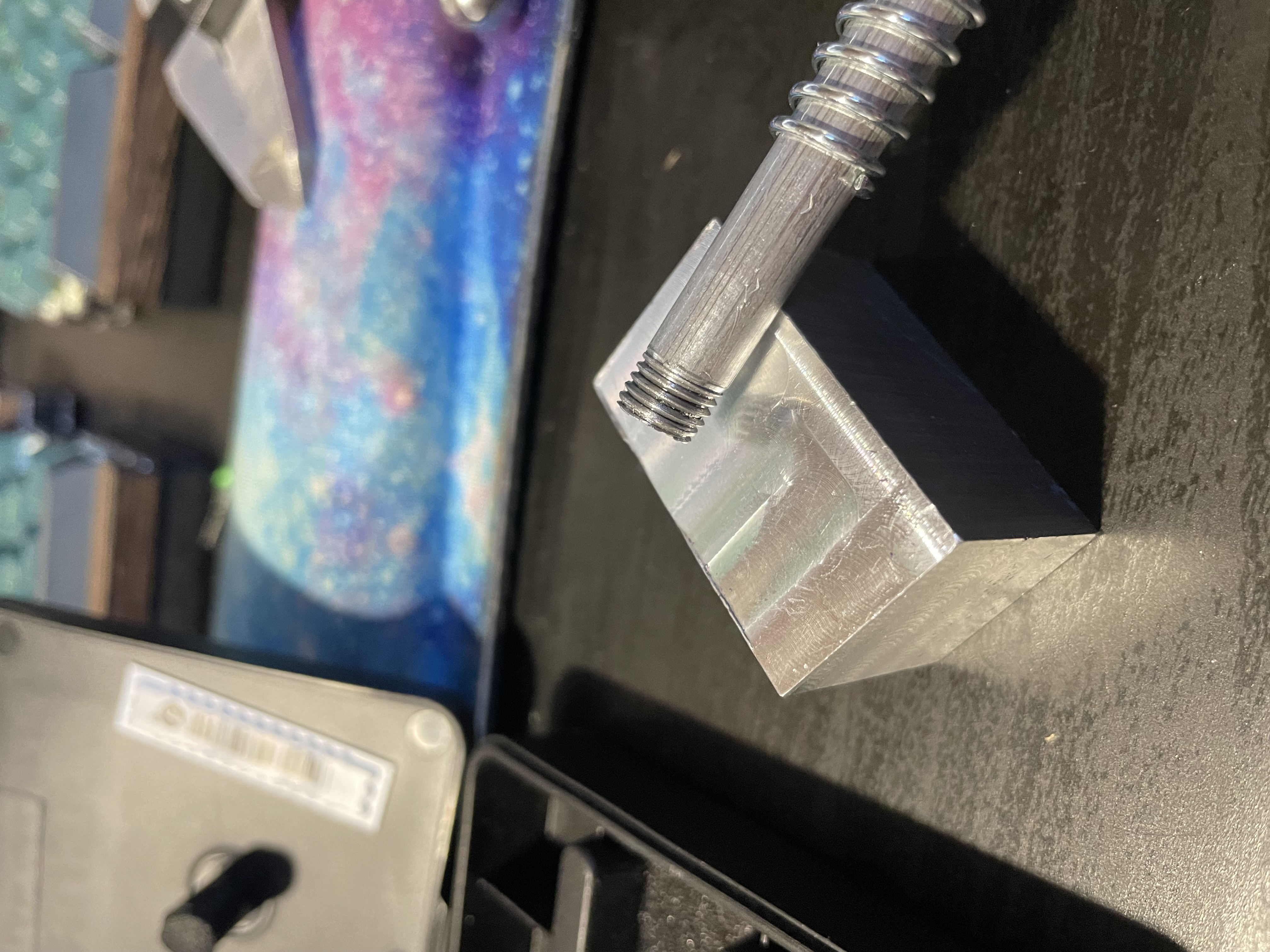
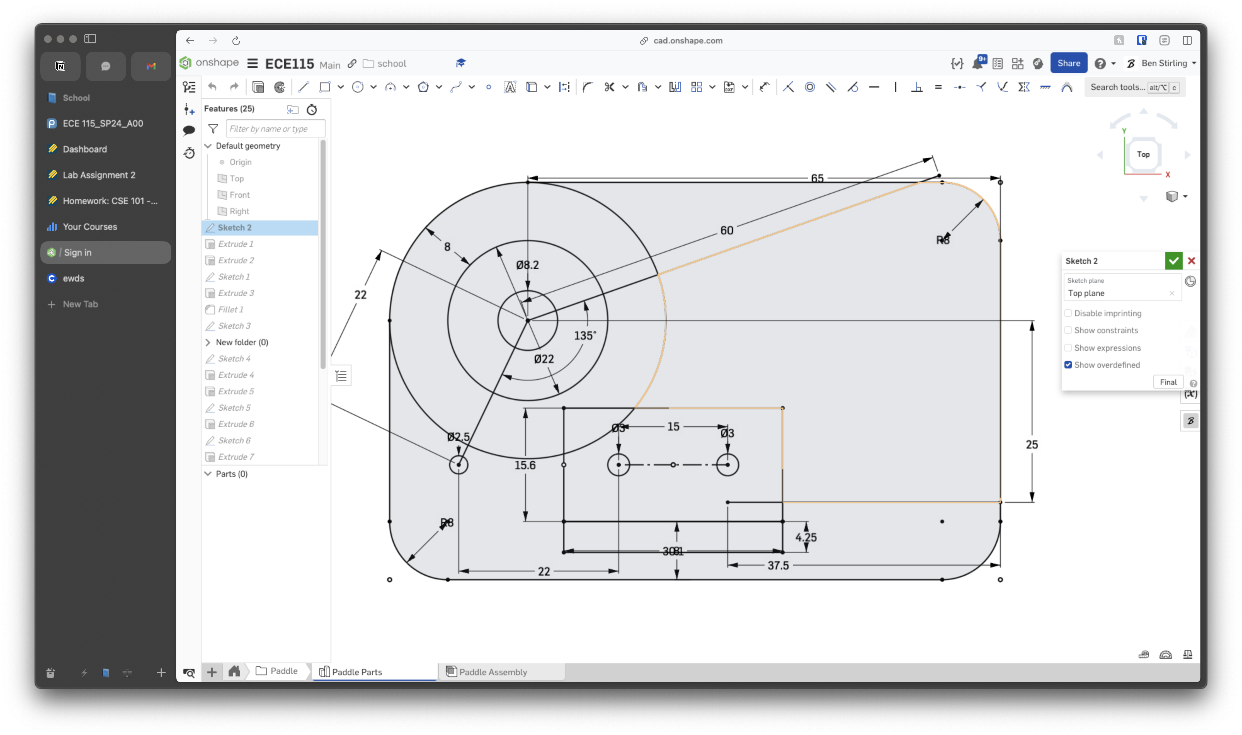
We started by prototyping the plunger mechanism.
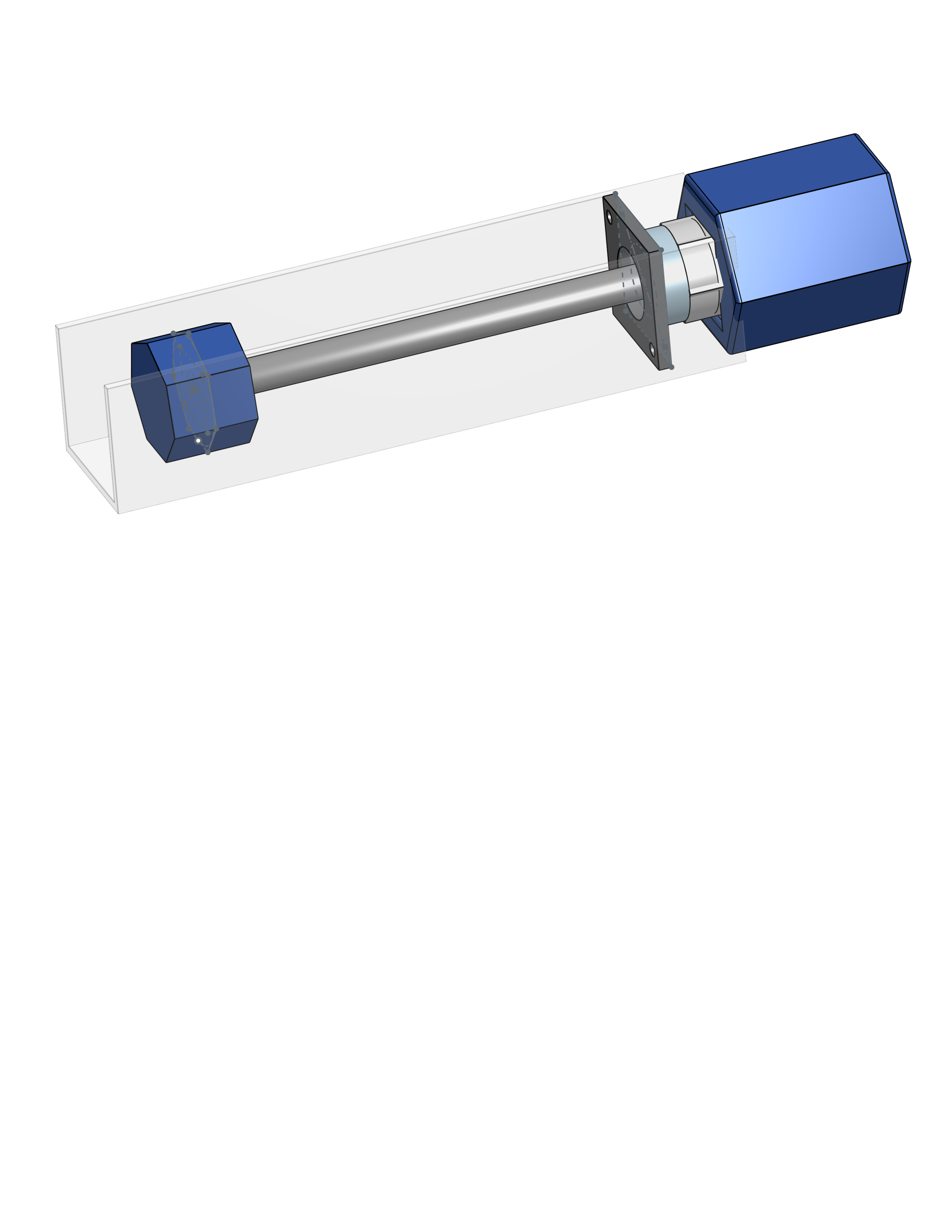
We ended up using 3D printed parts for the final plunger mechanism, and the threads turned out really nice. We did do some tapping and threading for the initial metal version that looked really nice.
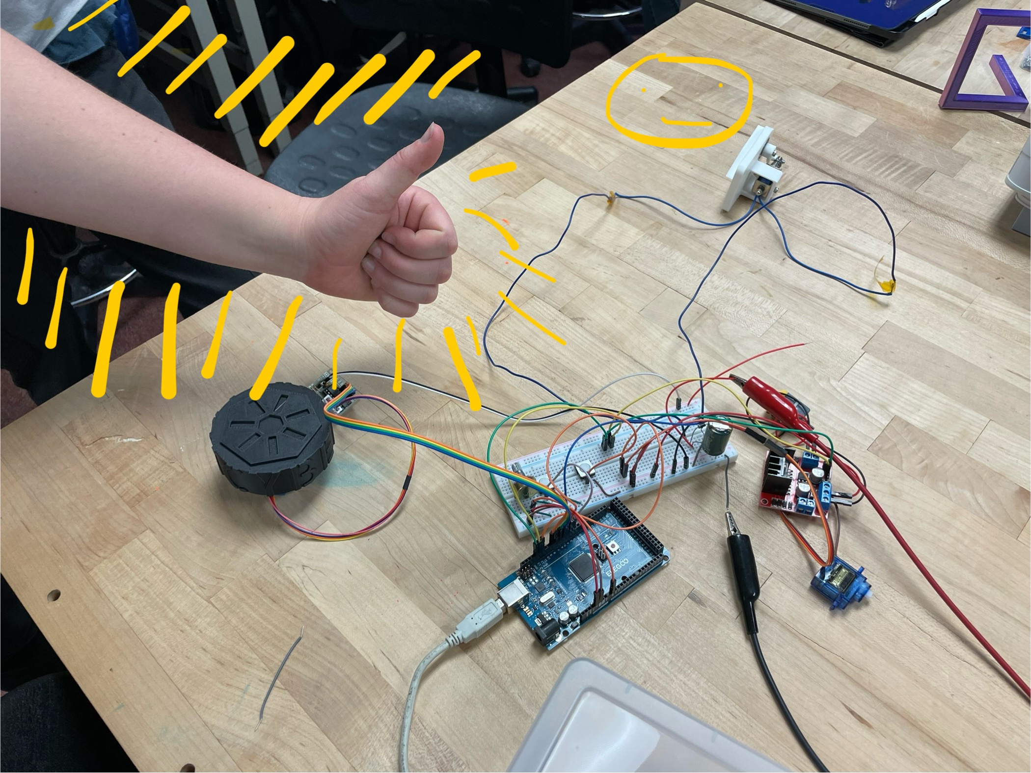
We moved onto some electronics and wiring which was a hot mess, but again, checked all the boxes. We did NOT use really much of what we did here in our final versions.
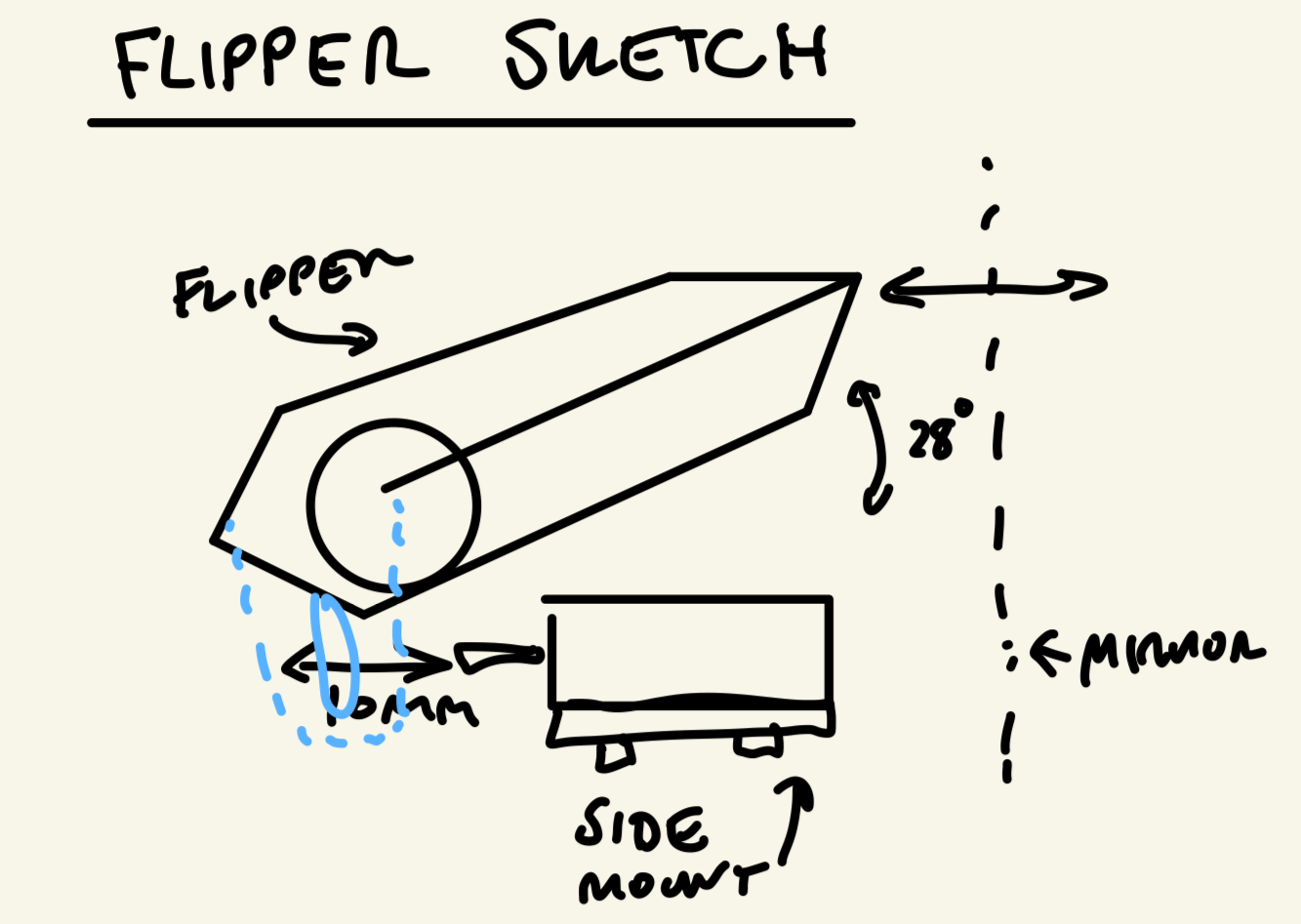
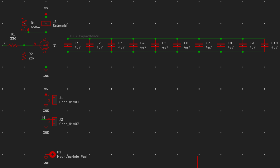
The paddles were a fun part of the project. We used a solenoid to actuate the paddles, and Adin designed a custom PCB for the solenoid driver.
Our schematic for the solenoid driver is below.
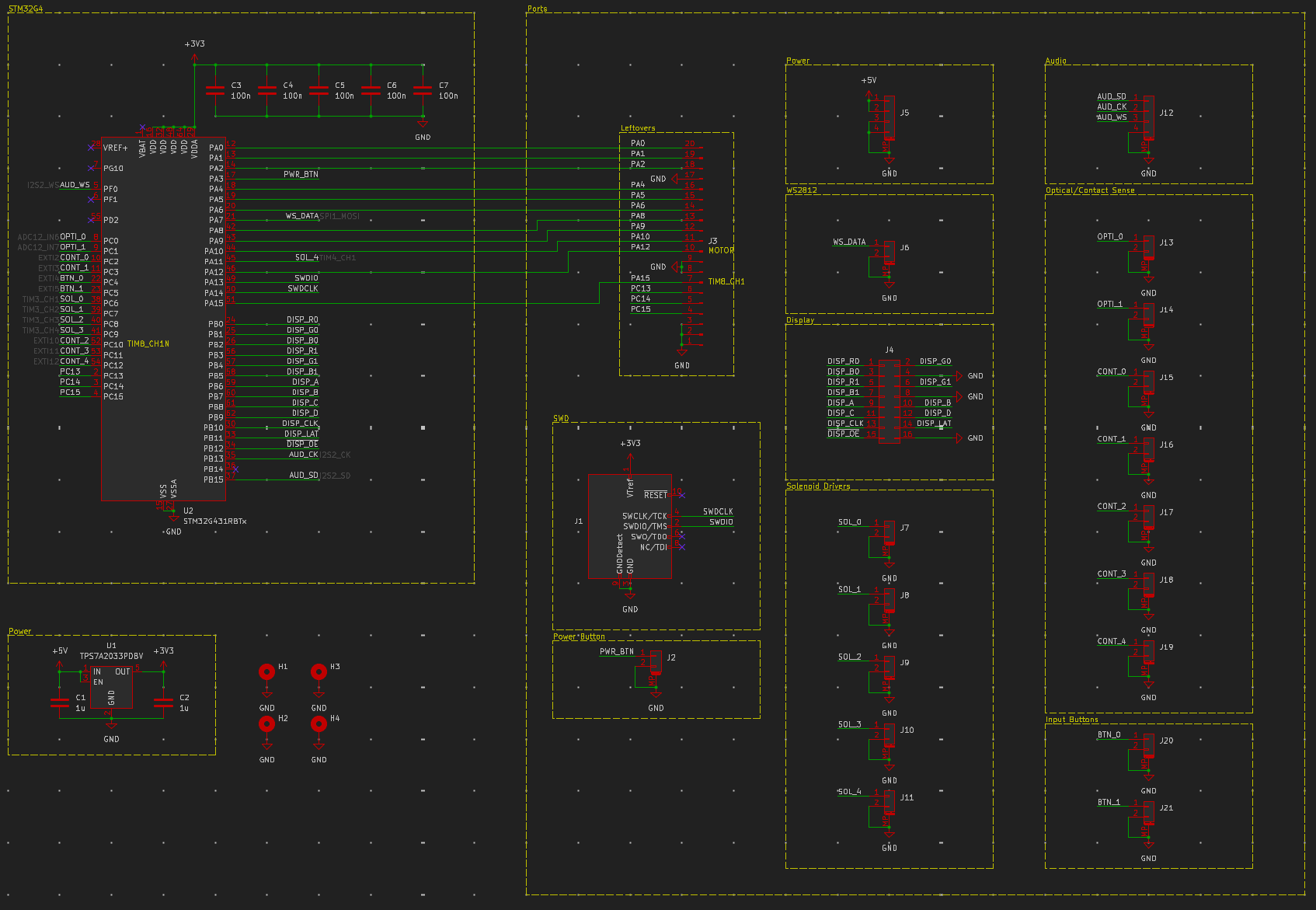
We also did a custom motherboard for the project, utilizing a STM32G4 microcontroller. Adin did a great job with the PCB design and programmed the microcontroller using Rust.
The wiring took forever, most of the time was us working together to land the 30 gague wire to the smd pads.
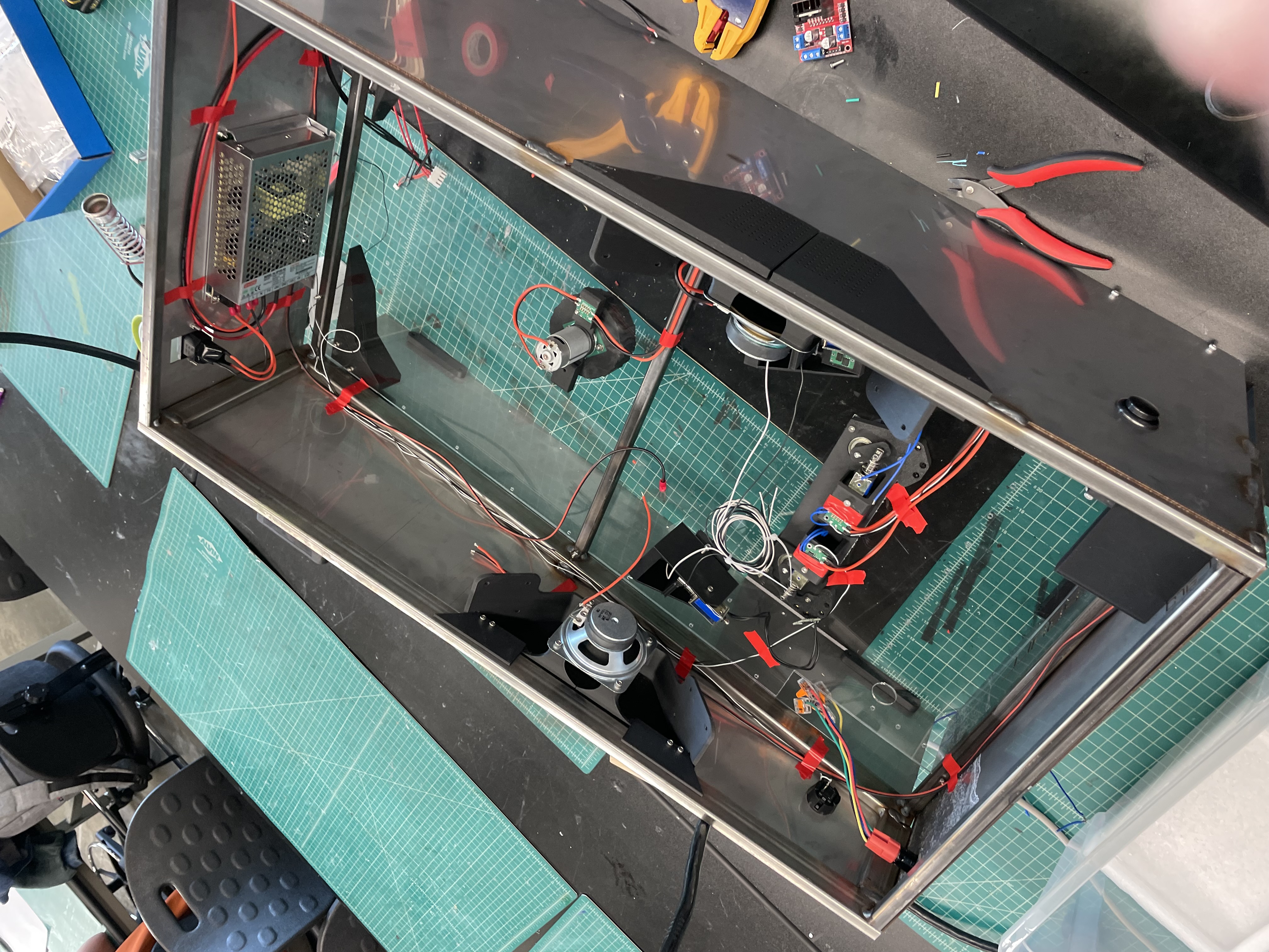
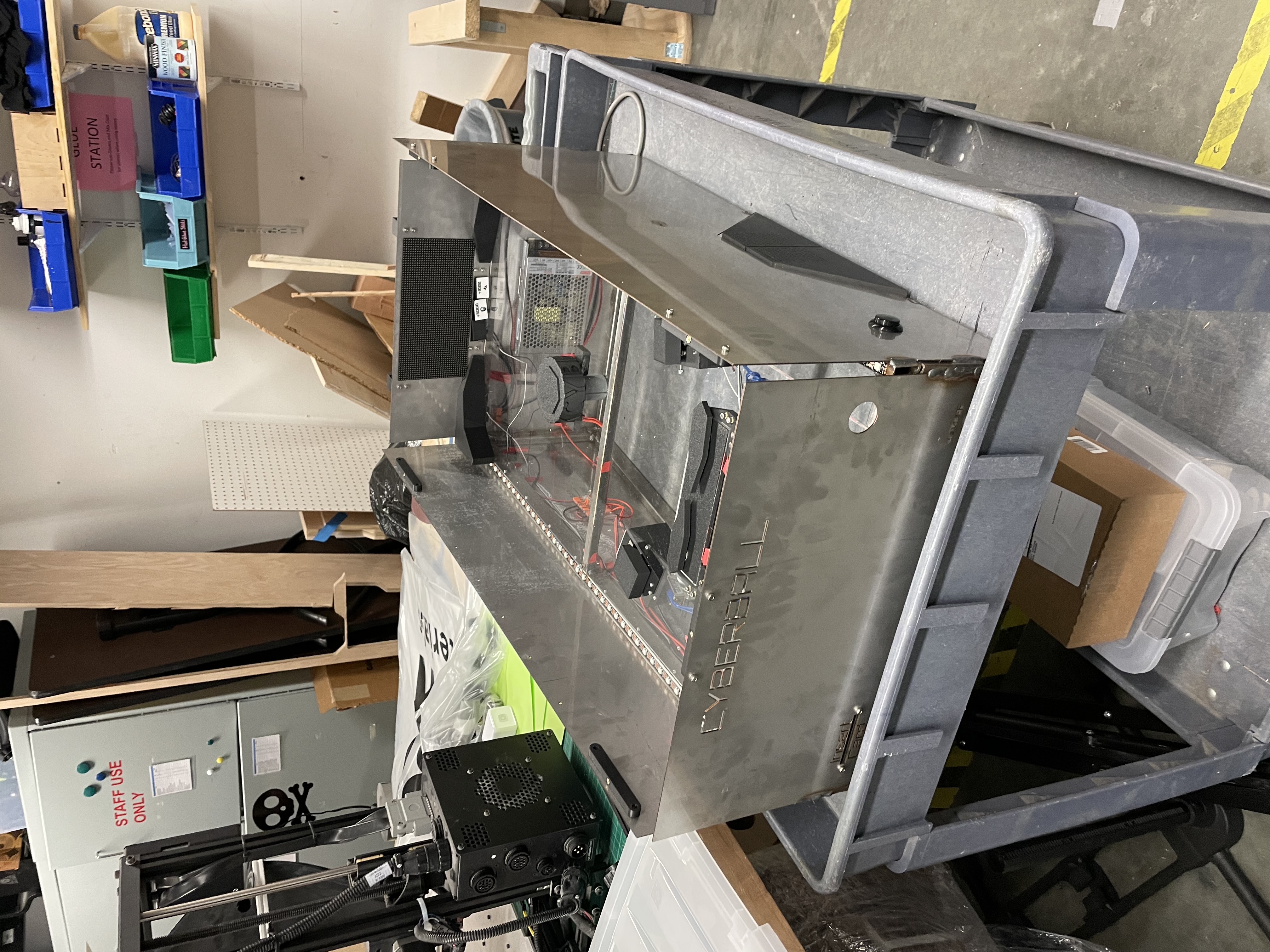
A nearly-assembled version ready to be programmed!
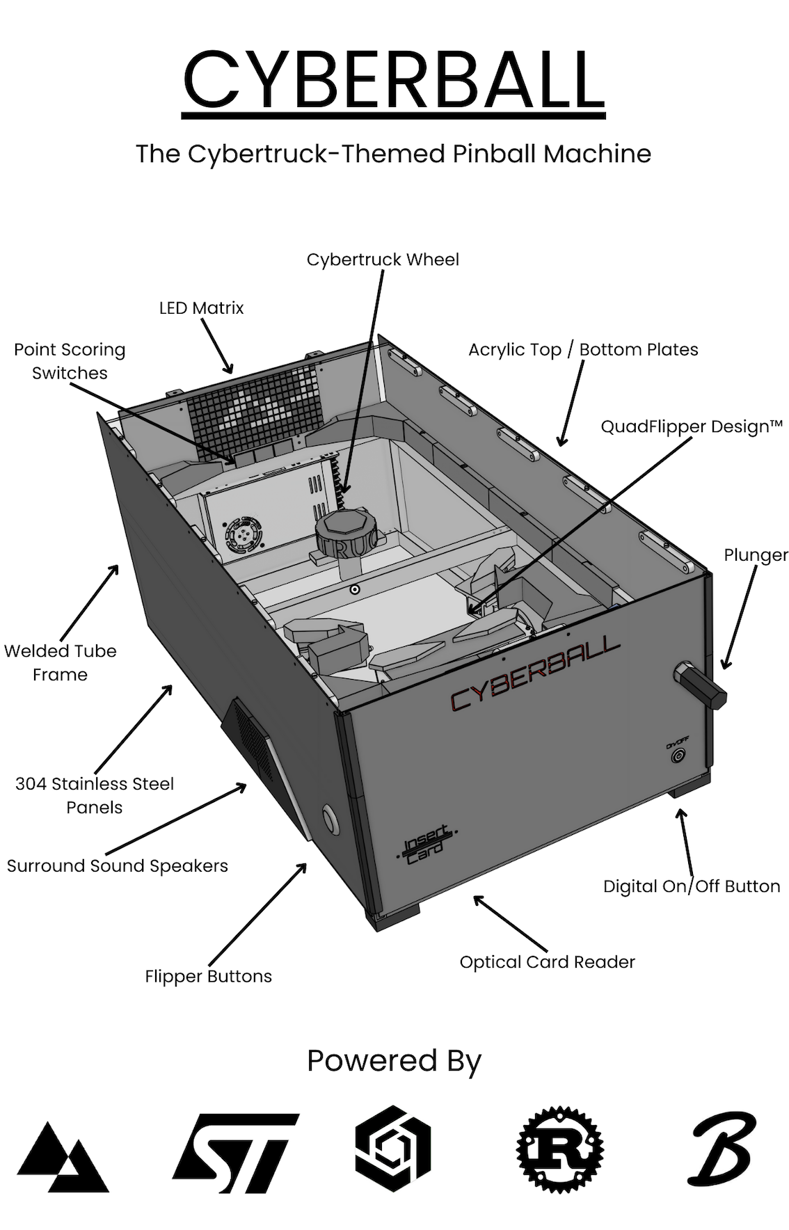
Instead of doing a technical report, we did a sick poster!
We had a TON of fun with this project. It was a great way to end college and (continue to) build a great friendship with Adin.